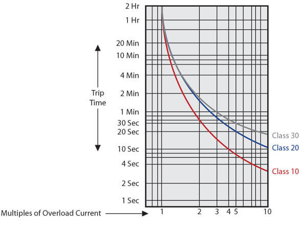
Thermal Overload Protection Formula
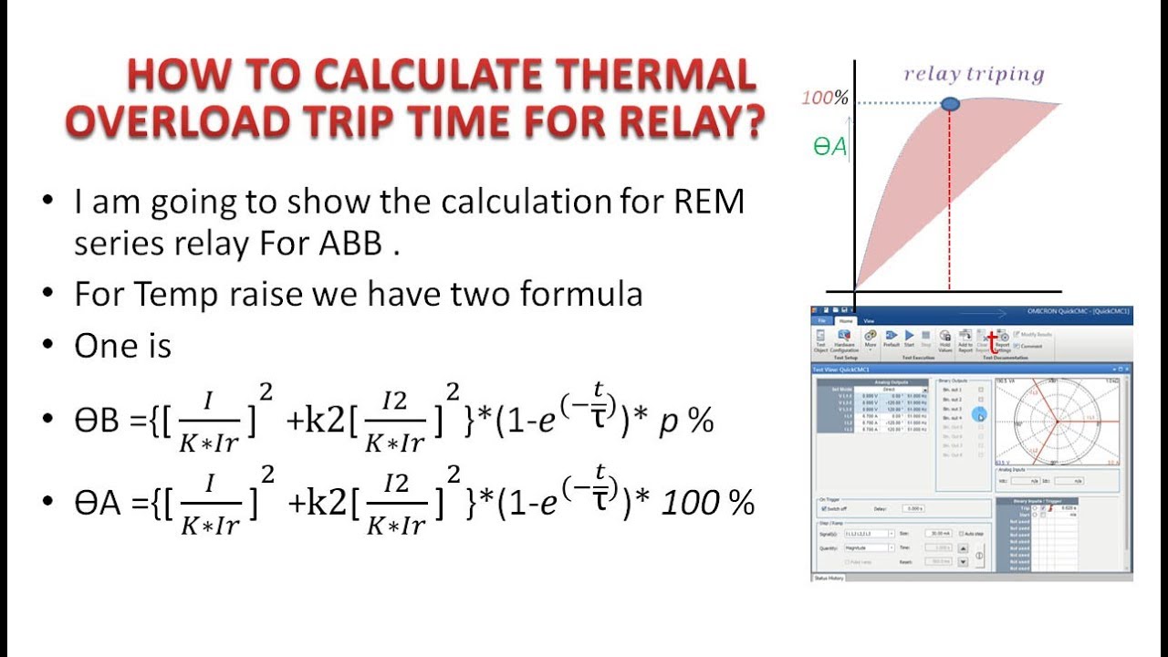
Motor Protection How To Calculate Thermal Overload Trip Time For Relay Youtube

Thermal Overload Motor Relay Protection
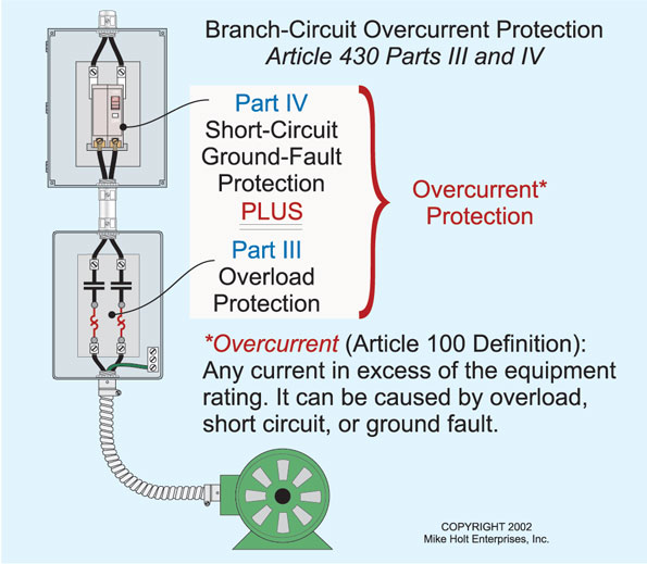
Motor Calculations Part 1 Motors And Branch Circuit Conductors Ec M

Protection Of Transformer Motor Generator Line Busbar Motor Protection
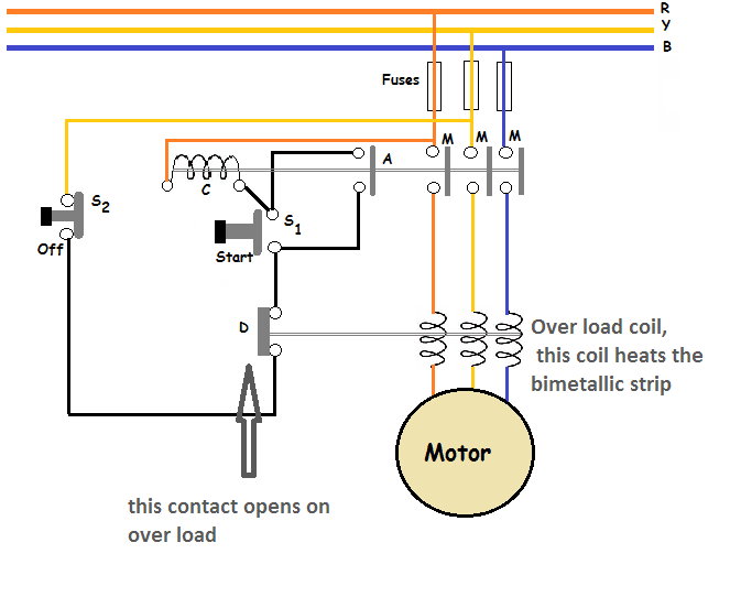
Thermal Overload Relay Working Principle Your Electrical Guide
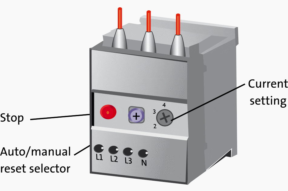
How To Know If You Set The Correct Current On A Motor Thermal Overload Relay Eep
R r θ dt dθ r r 1 s i c m r 2 8 s τ c m r 9 let r r u θ 10 and dt d r r 1 dt du θ 11 therefore the first order thermal model equation becomes the simple form.
Thermal overload protection formula.
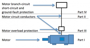
Motor Calculations Part Iii The Motor Overload Jade Learning
Http Prorelay Tamu Edu Wp Content Uploads Sites 3 2017 04 The Necessity And Challenges Of Modeling And Coordinating Microprocessor Based Thermal Overload Functions For Device Protection 1 Pdf
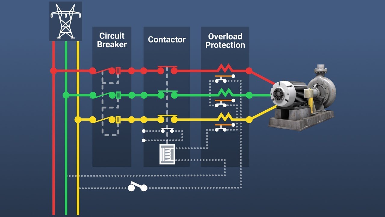
Motor Overload Protection Youtube

Motor Thermal Overload Protection Electrical4u
Source : pinterest.com
